At most of the places that I have worked (and datacenters that I have visited) the physical security has been provided by proximity cards. These are the badges that companies provide that you swipe at a door reader and the door magically unlocks for you. Most companies place a great deal of trust in these systems and view them as secure and unhackable. Unfortunately this is not the case -- all that one needs to do is walk past someone with one of thse badges and you can stel the secret number from the badge.
I decided to build just such a device.
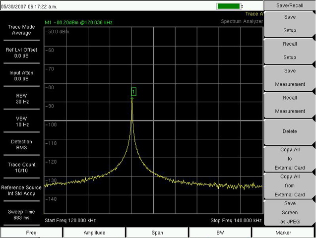
I began by taking a few proximity cards apart to see what all was inside -- not very surprisingly there is a coil that gets excited by the reader on the door (to provide power), a small capacitor to store the power and a small epoxy potted chip on a sliver of PCB. There are a few extra contacts on the board that I am assuming are used to burn the serial number onto the tag. I hooked up an oscilloscope to some of the contacts and energized the tag by placing it near the reader. The scope that I was using wasn't a particularly great one, but I did manage to collect a fair bit of useful info from this simple experiment -- the tags run at around 134Khz and that the signal the tag modulates doesn't look too complex. I also discovered that I could get access to a much cleaner signal from some of the other contacts than I could by reading off the antenna contacts. My Fluke scope does have software to download the waveform from the scope but it is Windows software (and I seem to have misplaced the disks) so I ended up just taking a photo instead.
HID Card with contacts broken out for testing.

Picture of captured waveform

Armed with this information I decided to see if I could build a device to clone a proximity card. I had an old Motorola card reader and I figured that I should be able to salvage the RF section and the bits that digitize the received signal. I pulled it apart and spend a large amount of time trying to reverse engineer the circuit and find where best to tap the signal. The circuit is really ugly and has a bunch of hacky stuff. Eventually I found some Schmitt triggers that clean up the signal and managed to get a fairly clean signal from them. Around that time we decided that we were moving from California back to Virginia and so I had to pack up my workshop and abandon the proximity card stuff for a while....
Motorola Logic Board

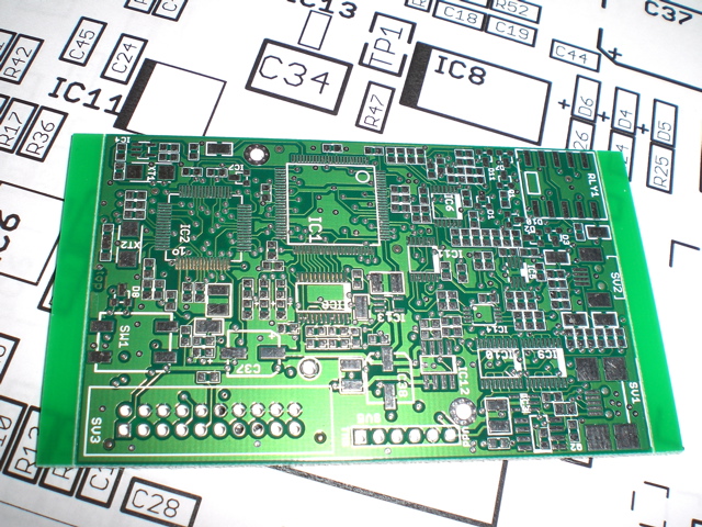
I then came across an article about a device designed by Jonathan Westhues called the Proxmark that did basically exactly what I wanted to do. I managed to contact him and after a few tries manged to convince him that I was really interested and not just some random crazy. After a while more I managed to convince him to share schematics and eventually to sell me a few blank boards. When the boards arrived I was still living in an extended stay hotel in San Jose (we had sold our place in California but hadn't moved to Virginia yet) and so couldn't actually do anything with the boards yet, After we moved to Virginia it took me a few months to get my office / workshop set up again. Once my office was setup and I bought all the bits from Digikey I finally got to start building the device. I have done some surface mount work in the past, but nothing quite this ambitious (the FPGA and Atemel processors have very closely spaced leads and the capacitors and resistors are 603s (6 thousands of an inch by 3 thousands of an inch)).
Blank Board
There are some tricks to hand soldering SMD components with lots of leads:
- Make sure the board is really clean -- I clean them with acetone and then 99.999% pure isopropyl alcohol to remove finger oil, etc.
- Light! Lots of it! I have 2 halogen desk lamps that I use to illuminate what I am doing. This is very important.
- Good quality flux and silver bearing solder are really important.
- A good quality fine tip soldering iron with a clean tip is a necessity. I have tried many brands but have settled on a Hakko Future Product 102 (ignore the silly name, it is a great iron!). Weller and Metcal also make nice irons, but the Hakko seems to keep a much more stable temperature.
- Pre-heating the board and component means that you don't need to add too much heat to melt the solder. I put mine on a pice of ceramic on an electric coffee cup warmer (see photo below).
- Put a blob of thick flux paste under the component to help stick it down and carefully rotate it so that is as close to aligned as possible, then solder one of the corner leads down. Do the final alignment and then solder down one of the opposite corner leads.
- Put some solder paste in a syringe with an applicator needle (I use Kester R276 solderpaste, available from Digikey) and apply a very thin line down one side, then run a clean iron tip along the pins. The first few times you do this you will probably put too much solder on and will end up with bridges between pins. Ignore them for now and do the other 3 sides.
- Go back with some solder braid and use it to remove any bridges -- the solder braid will almost definitely not wick the solder from under the pins, but you can apply a very very thin line or dot to suspect pins and resolder them.
Spartan II FPGA and too much solder on coffee cup warmer.
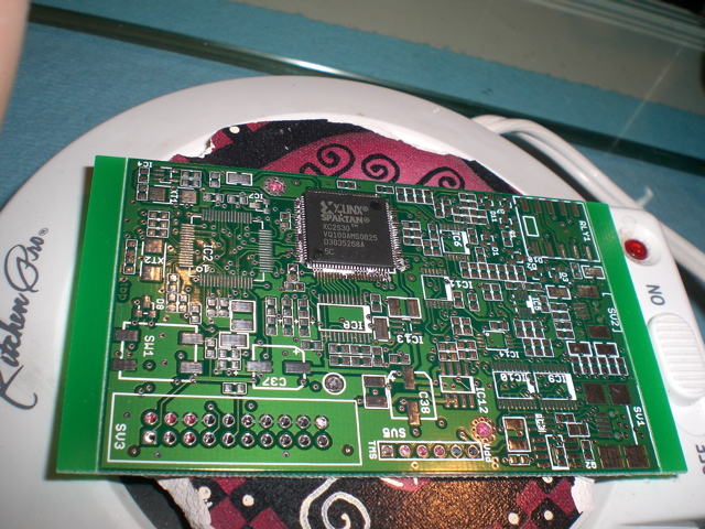
This picture shows the Spartan II FPGA mounted on the board. The board and component are preheated on a piece of ceramic on an electric coffee cup warmer. The ceramic was originally one of those porus coasters that I cut to fit with a hole-saw on a drill-press. This solution heats up the board and component to around 130o to 140o Fahrenheit and makes the solder and flux flow much better when you heat them with the soldering iron. As you can see I have way to much solder and went back with some good quality solder braid to wick away the excess.
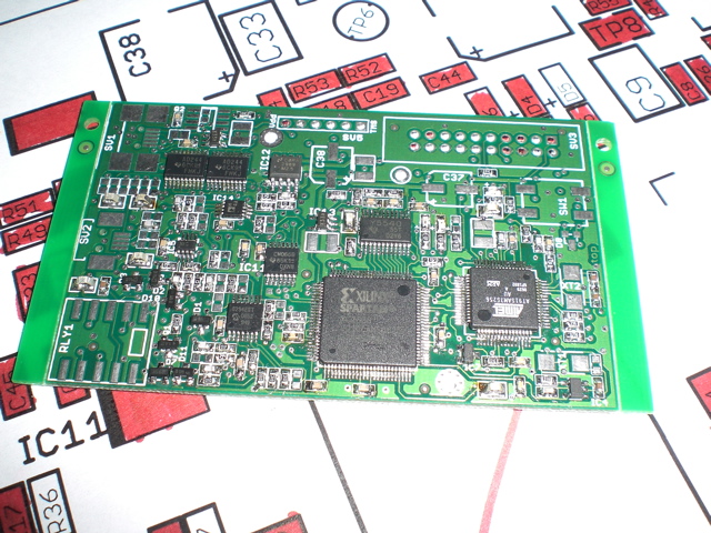
All ICs mounted
 of the ICs mounted")
In this picture most of the ICs have been mounted. The FPGA is the big IC in the top middle of the board and the Atmel AT91SAM7S256 (ARM7) processor that drives everything is in the top left. The ARM7 processor is a great device. It is a 32-bit RISC processor running at 60MHZ. It has 256KB of embedded flash and 64K of SRAM. It has a built in voltage regulator so it can be run from a single 3.3V supply and has integrated peripherals including (lifted from Atmel's site): USB 2.0 Full Speed Device Port, USARTs, SPI, SSC, TWI and an 8-channel 10-bit ADC. Its Peripheral DMA Controller channels eliminate processor bottlenecks during peripheral-to-memory transfers. Its System Controller manages interrupts, clocks, power, time, debug and reset, significantly reducing the external chip count and minimizing power consumption.
The best part is that the device is very easily to develop for -- you program it in C and then use GCC to cross compile for it.
Applying solder paste to solder down some resitors

Some of these components are really SMALL!
Board with most SMD components mounted
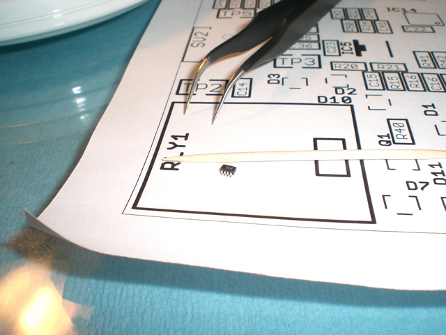
This is the board with most of the surface mount components mounted. I print out the component placement diagram (or sometimes copy and enlarge the actual board) whenever I build something with lots of components and then fill in the components that I have already mounted to make sure that I am not missing anything. This board is almost done. It still needs the connectors, some of hte (physically) larger capacitors, the relay and the button.
I still need to insert the pictures of the most finished device here...
Dead Bugs!
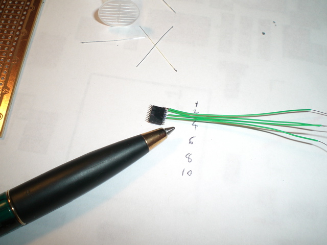
Once I was done building the device itself I needed to program the initial bootloader onto it. The Atmel processor has a JTAG interface and the board is cleverly designed with a standard 20 pin JTAG interface. Unfortunately I don't actually have a JTAG interface and so had to build one -- luckily I had the required components (or close enough!) handy and so could whip one up a Wiggler compatible device. The chip that I used was a really small and I didn't have a board to mount it on, so I had to build it in "dead bug" style. Seeing as this plugs directly onto a PC Parallel port I was somewhat nervous about shorts and frying the notebook, but managed OK.
Once the device was all build I hacked the software some (I am much more of a software person than a hardware person). I changed the software so that the button switches the device between various modes and provides feedback via the 4 LEDs. Eventually I want to remove the LEDs and reuse the outputs to drive an LCD to provide better feedback about what is happening. For now I have it so that the first press of the button makes the device read a tag, the second press plays back the samples waveform. The next press demodulates the signal into an HID style format and subsequent presses make the device play back the demodulated signal. If you hold the button down to > 1/2 second it goes back to the initial state.
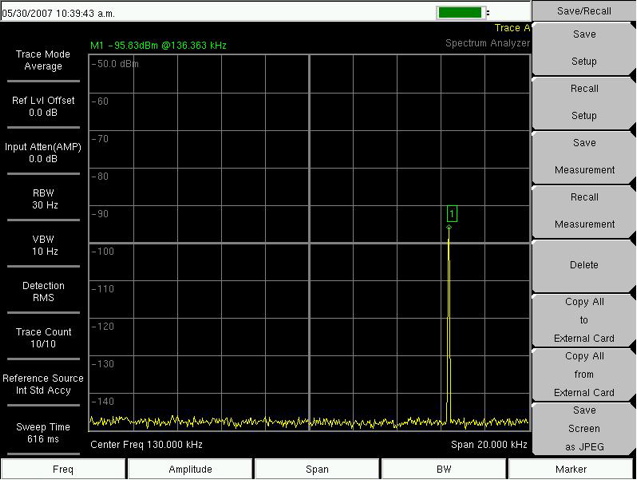
I took a spectrum analyzer and took some measurements from various readers
HID ProxPro proximity card reader
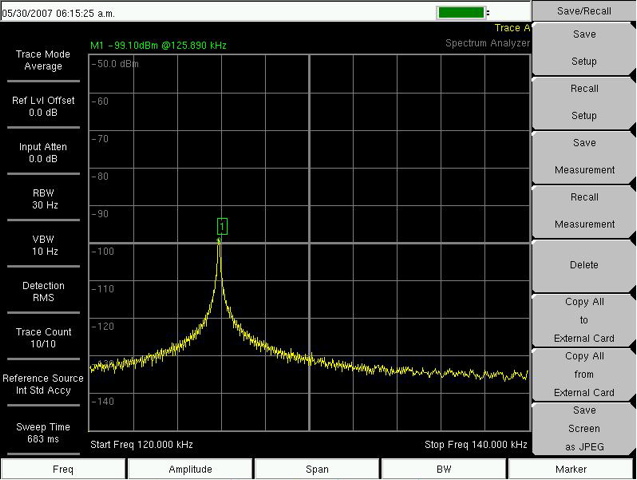
Kastle Proximity reader