While going through some old electronics I found a pager that I wasn't using any more and I decided that it would be interesting to see if there was still any data being transmitted on the pager networks -- I also decided that a pager would make a really good remote receiver for things like home automation. They are fairly cheap, get reasonable reception in most places and (internally at least) have a digital signal.
I popped it open and looked around to see if I could find a decoded digital signal, but it looks like there is basically an RF section that feeds a single processor that does of decoding, checking for address match, etc. I briefly considered trying to find a JTAG type interface, pull the firmware, disassemble it, etc but that sounded like way more scrummaging and groveling than I wanted to do. I decided to instead just read the output of the FSK IF detector and implement the FLEX or POCSAG in software -- this would allow me much greater flexibility in the future as I could create my own network, watch messages (obviously only ones that I sent, reading messages for other folks is illegal), etc. Initially I figured I could just hook a microprocessor to the output of the FSK IF detector (a Toshiba TA31149FNG) and bit-bang the input. After reading the TA31149 data-sheet I discovered that it is a 4-level FSK and not a 2-level FSK. While I could still do this with a microprocessor I decided that the timing might become a little hairy, so I decided to take the 2-bit output of the 4-level FSK and use an FPGA to convert it to a RS-232.
I have some of the really nice Pluto-II FPGA development boards from www.knjn.com -- they have an Altera's Cyclone EP1C3T100 and a 1Mbits FPGA boot-PROM. They also are programmable through a serial port and Altera has a free set of development tools. After some poking I managed to implement a very simple phase locked loop in the FPGA that takes the 2-bit output, removes some noise (the FPGA liked to clock on the overshoot, noise, etc), collect 4 samples (2 bits per sample) and then output TTL level RS-232 which I can then do more decoding with later.
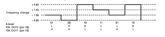
Here is the FSK freqency shift to 2-bit output diagram:
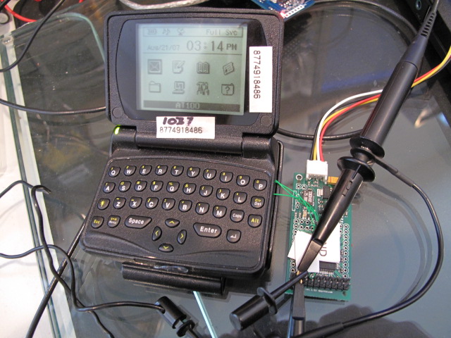
And the pager hooked up to the FPGA board and oscilloscope. The black, yellow, white and red wires are power and RS-232:
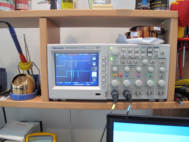
The scope showing the output from the FSK IF decoder (yellow, input to the FPGA) and the associated FPGA output (blue):

If I get a chance I'll post the Verilog source and some serial output from the FGPA. Once I get around to cleaning it up I'll also post the POCSAG decode source.